B+S
Location |
Client |
Service |
Category |
Completion |
Description
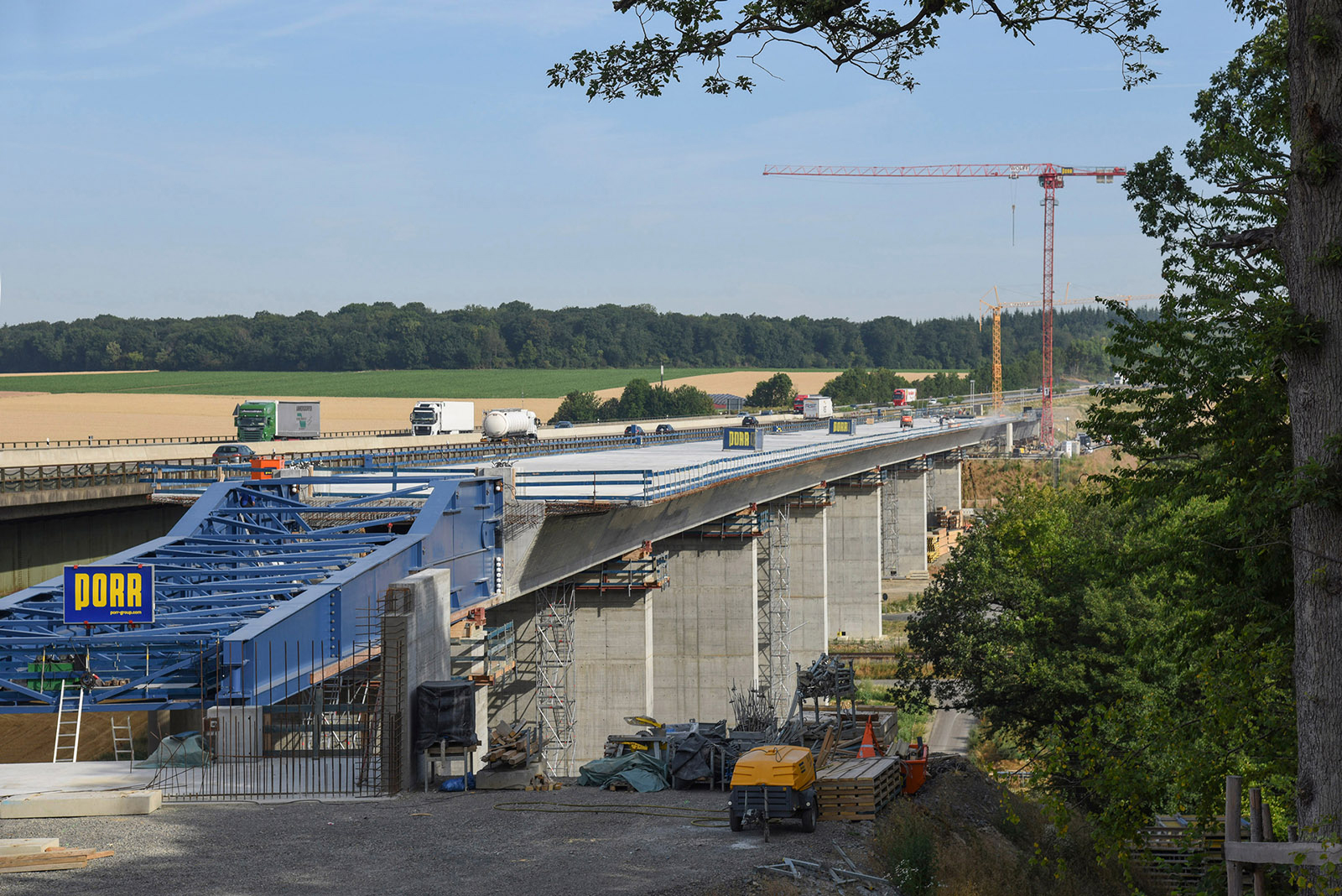
The Rothof Valley Bridge is located on the A7 motorway, approximately 15 km east of Würzburg. The structure carries the A7 motorway over the approximately 30 m deep valley of a stream, the Nuremberg-Würzburg ICE railway line, the Würzburg-Schweinfurt railway line, a municipal connecting road, and several farm tracks. The existing structure has damage (cracking and corrosion of the steel components, corrosion in the area of the concrete roadway slab, wire breaks in the transverse prestressing), which is why the structure is being replaced by a new replacement structure in the same location.
New construction and transverse displacement:
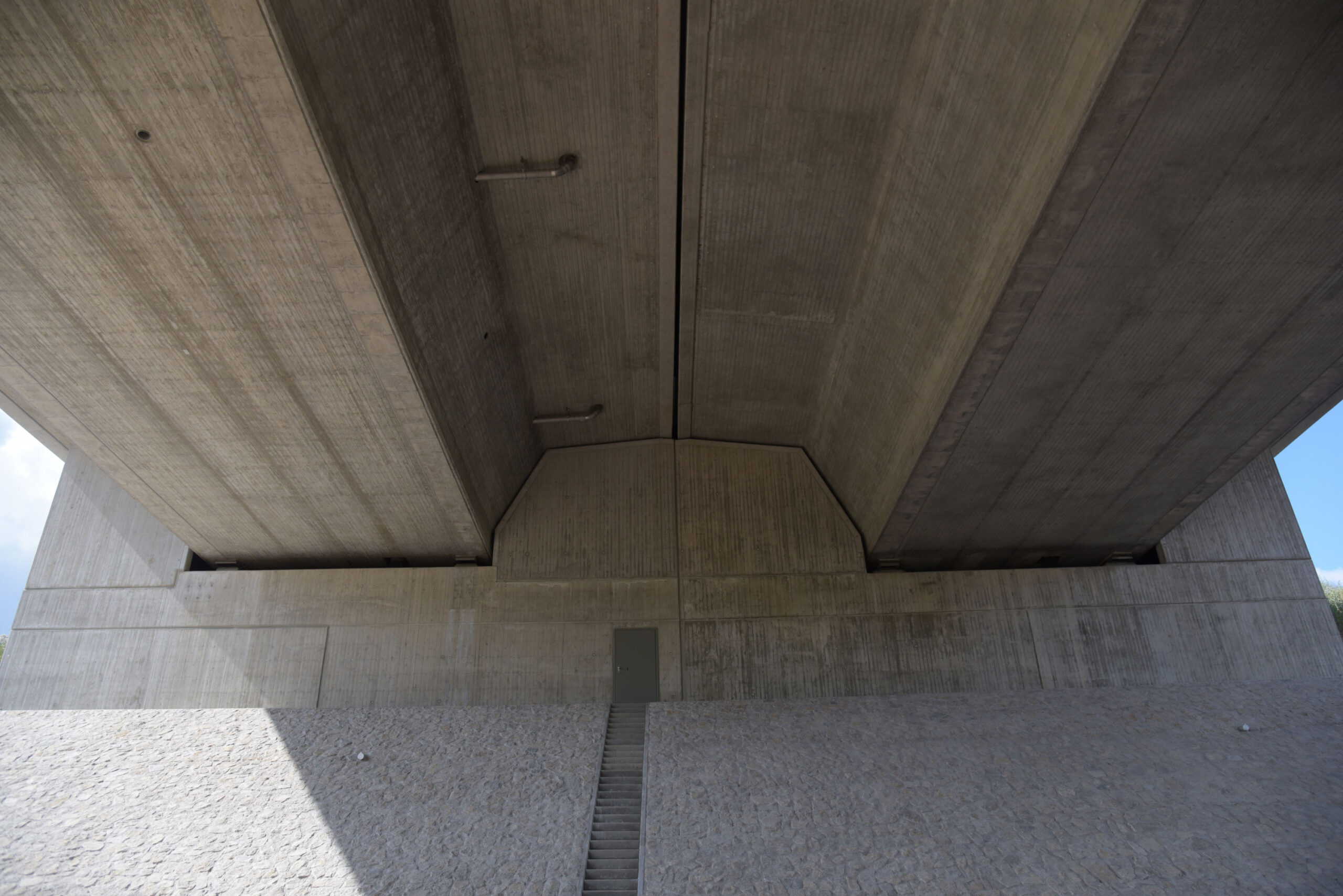
The directional carriageways are guided on two separate superstructures, each with single-cell prestressed concrete box girders. The carriageway slab width per super-
structure is 17.55 m, the width of the box at the lower edge is 8.0 m. The carriageway slab is inclined at 2.5%, the base plate is horizontal, and the 50 cm wide webs are inclined. The average height of the box section is 3.70m. The spans are 35.0 – 50.0 – 4 x 60.0 – 50.0 – 35.0 m. The superstructures
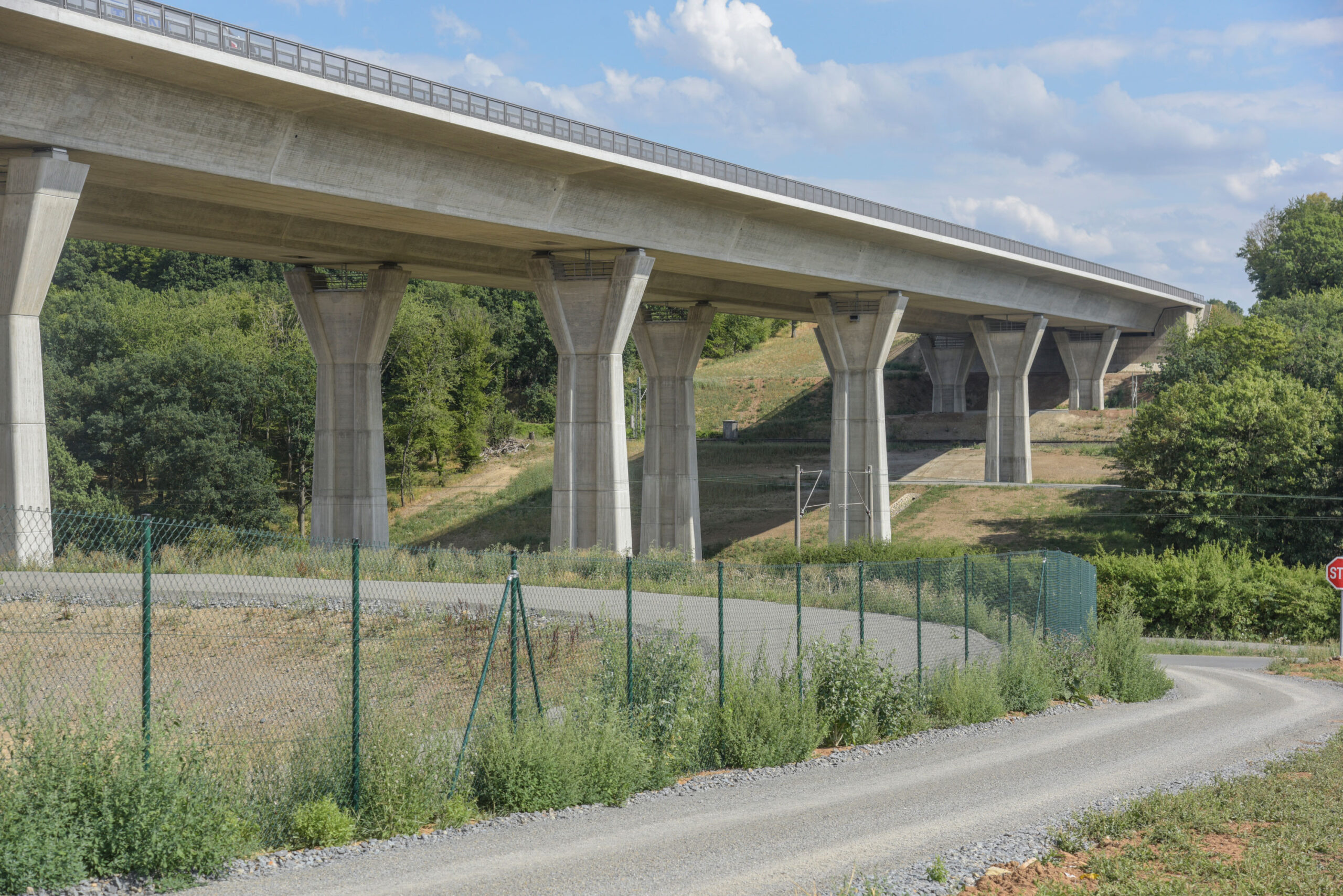
were manufactured using the incremental launching method without auxiliary supports, with 15 cycles per superstructure and a cycle length of 30 m. The production facility was located approximately 18 m behind the abutment axis 10 (WL Würzburg), and the incremental launching system was arranged on the abutment axis 10. The 36 m long cantilevered nose was extended and adjusted in width for the application. The inspection was also carried out in our office. The piers with a bone-like rectangular cross-section have a constriction approximately 6.30 m below the pier head. The cross-sectional width/length here is 4.00 / 1.70 m; below this, the pier has a taper of 25:1 or 40:1. The piers with heights between 11.70 and 27.80 m are founded on pile head slabs with a thickness of 2.00 or 2.50 m on 8 or 10 large bored piles with l = 12.50 m – 18.50 m and d = 150 cm in hard limestone, with the outer piles inclined at 12:1. To increase the load-bearing capacity of the piles, the alternative design as cast-in-place rammed piles with foot widening was tested.
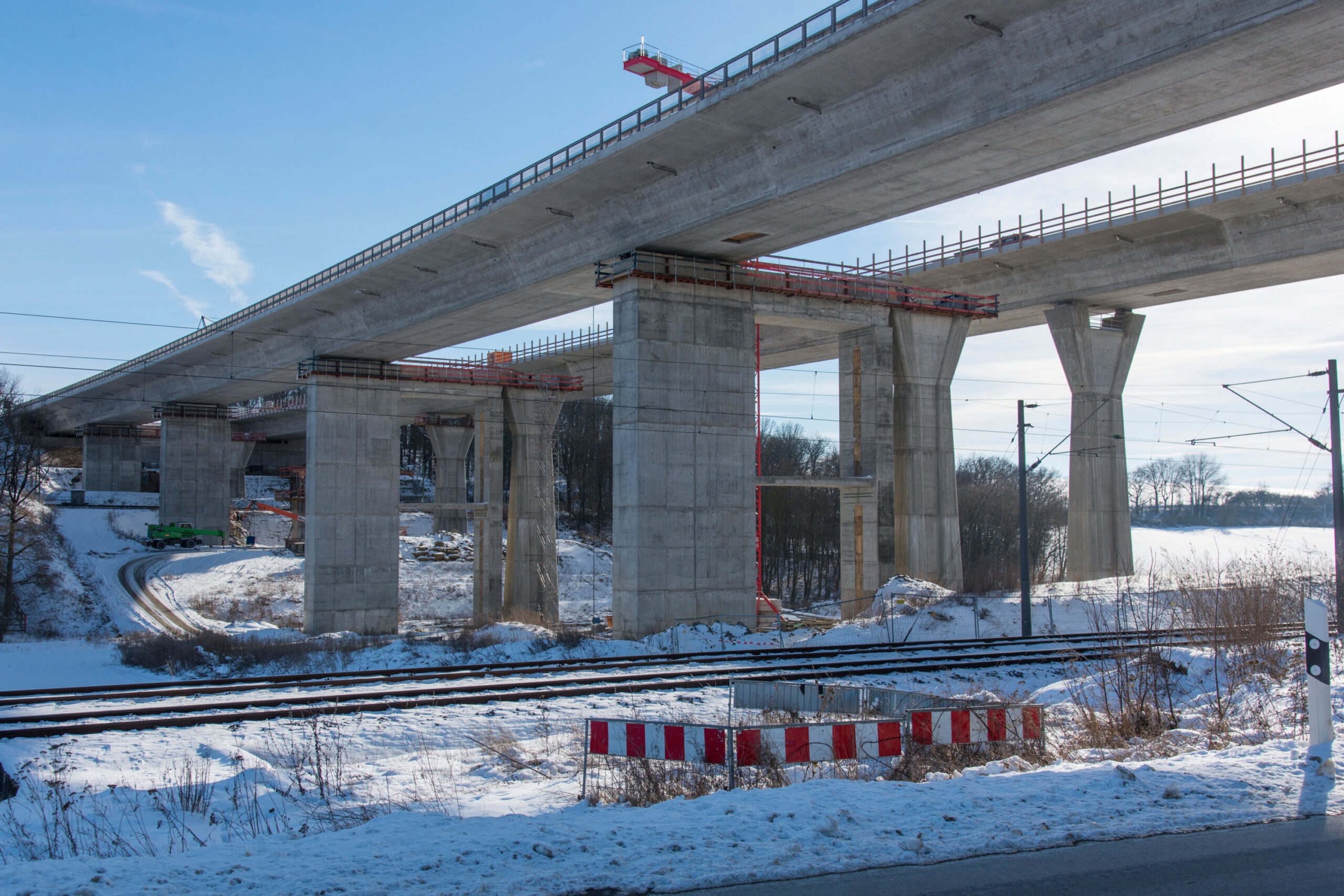
As road traffic on the A7 motorway had to be maintained at all times, the Fulda directional carriageway was constructed in a temporary replacement position next to the existing structure on auxiliary piers in the first construction phase. The temporary piers were constructed as reinforced concrete piers with a box section of 3.00 x 8.60 m and 30 cm wall thickness. The pier head with a thickness of 2.50 m was solid and made of cast-in-place concrete on a precast concrete element as permanent formwork. The temporary piers were founded with a 2.00 m thick pile head slab and large bored piles d = 150 cm in load-bearing limestone. The complete traffic routing of the A7 motorway subsequently took place via this temporary route and the existing structure was completely dismantled. Subsequently, the final substructures for both directional carriageways were erected and the second superstructure in the Würzburg direction was constructed. Finally, the superstructure of the Fulda direction, which was supported in a temporary replacement position, was transversely displaced into its final position. For the transverse displacement, an auxiliary pier as a pair of piers with a rectangular cross-section of 1.50 x 150 m was founded on the pile head slab of the pier of the directional carriageway next to each final pier of the Rifa Würzburg. This pair of auxiliary piers was connected to the temporary pier on the side position with an intermediate and a head beam. The transverse displacement track was arranged on the head beam. The transverse displacement distance of the 17,760 t heavy, 410 m long superstructure was 19.75 m.
Dismantling of the existing structure:
The dismantling of the single-span composite superstructure of the Rothof Valley Bridge was carried out by lightening the concrete roadway slab, then dismantling the secondary steel beams and finally cutting and lifting out the main beams. Auxiliary supports were required to support the partially dismantled superstructure, withwhich the superstructure could be supported via hydraulic presses with defined forces.When planning and inspecting the dismantling, it had to be taken into account that pre-deformations had been imprinted on the existing superstructure duringmanufacture [1]. The imprinted pre-deformation causes arelief of the compression area of the main steel beams, which meant that they could be manufactured very economically in terms of material during the construction of thestructure at that time. When calculating the dismantling conditions, the associated stress state imprinted in the supporting structure had to be taken into account in orderto accurately determine the overall stresses and to avoid overstressing the top chord of themain beams. In the course of the dismantling, it was necessary to maintain residual cross-sections of the concrete roadway slab above the webs as compression chords in order to avoid overstressing the steel structure
in the partially dismantled state.
Special features
The dismantling is carried out by lightening, cutting and lifting out.
The replacement structure is planned using the incremental launching method (without auxiliary supports). The BA1 superstructure is manufactured in a side position with subsequent transverse displacement.
To increase the load-bearing capacity of the piles, the alternative design as cast-in-place rammed piles with foot widening is being tested.