B+S
Location |
Client |
Service |
Category |
Completion |
Description
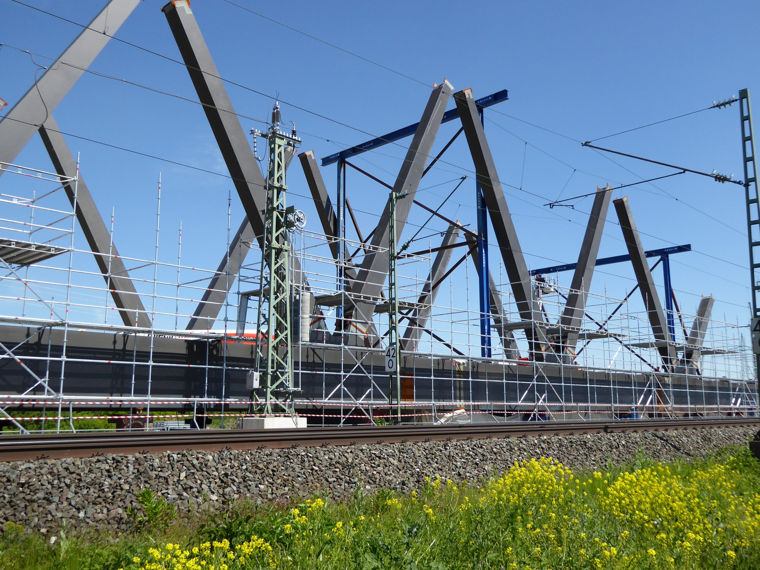
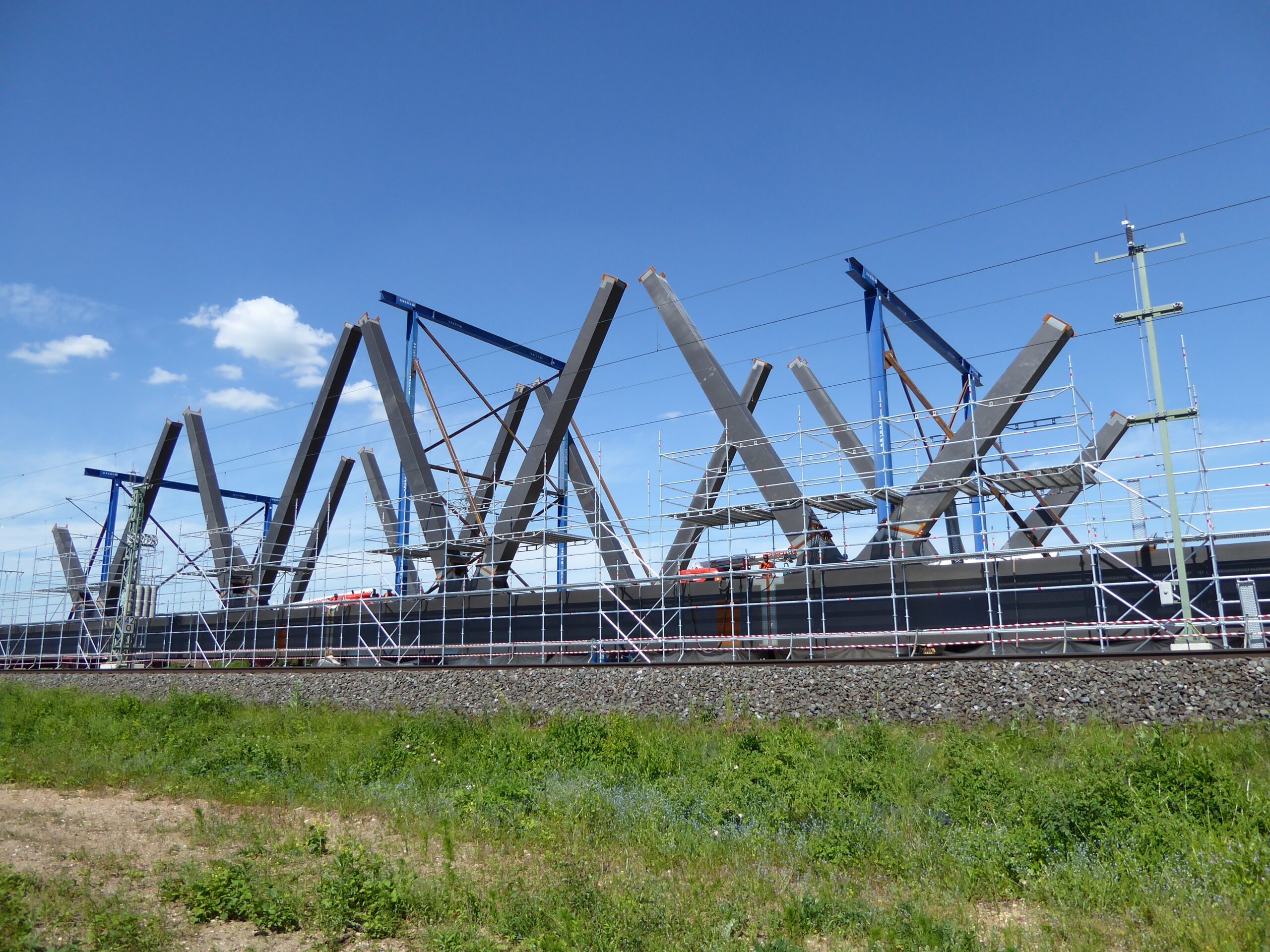
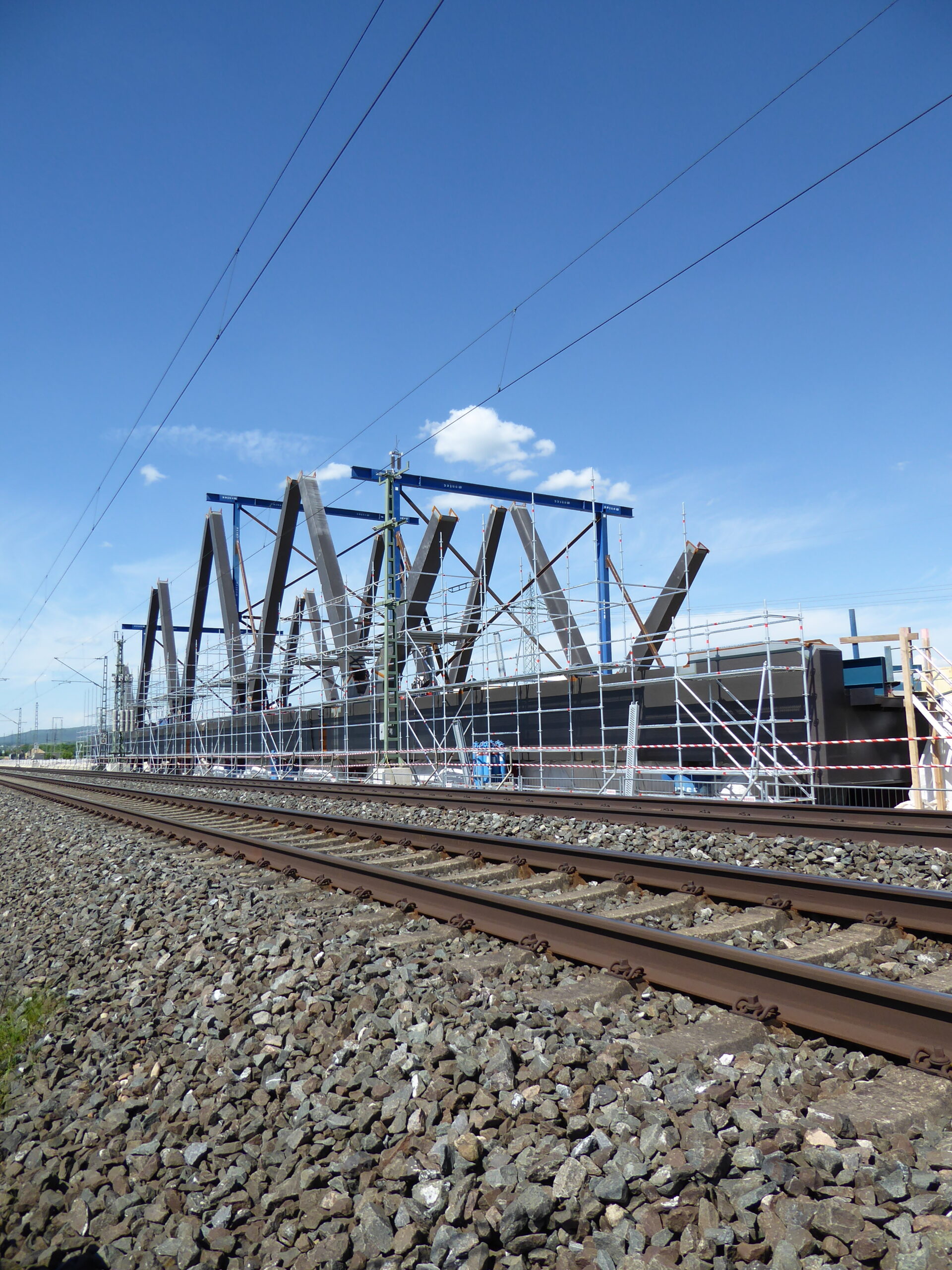
The subject of this reference is two railway overpasses over the existing BA 73. The structures are being built as part of the four-track expansion in PA 19 Forchheim – Eggolsheim of the ABS Nuremberg – Ebensfeld: The Nuremberg – Ebensfeld expansion line is part of the Nuremberg (- Ebensfeld) – Erfurt – Leipzig/Halle – Berlin railway line. To the south, it connects directly to the Erfurt – Ebensfeld new construction line. The ABS Nuremberg – Ebensfeld is part of the Berlin – Palermo railway axis, which is to be continuously upgraded for high-speed traffic as Project No. 1 of the Trans-European Network (TEN). The 83 km long expansion line connects the cities of Nuremberg, Fürth, Erlangen, Forchheim (Upper Franconia) and Bamberg as well as the municipalities along its route in the Nuremberg metropolitan region. It offers connections to other local transport services within and outside the region. It also includes the four-track expansion through the new construction of the 5919 Eltersdorf – Leipzig line for a speed of up to v = 230 km/h, including the upgrading of the existing 5900 Nuremberg Hbf – Bamberg and 5100 Bamberg – Hof to Ebensfeld lines for a continuous v = 160 km/h. Lines 5919 and 5900 or 5100 are bundled and will run parallel to each other in the future. As part of the four-track expansion in PA 19, DB Netz AG – Major Projects VDE 8.1.1 is building several engineering structures. These also include the railway overpasses over the existing BA 73.
The two superstructures of the four-track railway overpass are designed as single-span bow arch truss bridges with a clear width of 88.00 m. The supporting structure of the two-track bridge structures is divided into two steel truss levels with lower chord girders, curved upper chord and symmetrically arranged truss diagonals. All supporting elements of the truss levels are designed as closed box sections with a uniform width. A girder grid with an orthotropic road deck is manufactured between the lower chord girders to accommodate the ballast superstructure. The structure carries the railway lines 5900 and 5919, each with two tracks, at an intersection angle of 36.3 gon over the existing BAB A73. The structure itself has a skew angle of 100.0 gon. The distance between the bearing axes is 90.00 m. The arch has a variable height of approx. 2,000 mm at the arch start and 1000 mm at the apex of the arch. The arch levels are located on the outside next to the road. The arched upper chords, the lower chords and the end cross girders are manufactured as box sections. The lower chord or stiffening girders are rigidly connected to the arches by means of truss diagonals. There are 8 diagonals per arch, which are arranged on the lower chord girder at intervals of 21 – 3 x 16 – 21 m. The intersection distances on the arches vary between approx. 13.30 and 16.00 m and increase from the base point to the apex. Cross girders with a spacing of 2.00 m span between the lower chord or stiffening girders. These are designed with a variable height between 1.20 and 1.32 m in order to map the cross slope of the road deck. The clear distance between the stiffening girders and arches is a constant 11.70 m perpendicular to the bridge axis. The truss diagonals are rigidly connected to the lower chord or stiffening girders and the arches. A diamond bracing with a final portal frame is arranged between the arches for stabilization. The bracing bars are made with square box sections and are connected to the arch sections in an articulated manner. The intersection points are designed to be rigid. The road deck is formed with longitudinal ribs made of flat steel and cross girders. The gradient high points are located outside the structures and form a horizontal gradient in the area of the bridges. The superstructure is designed as ballast. The tracks run straight over the
bridge structures without curvature. The service paths and cable ducts on both sides are designed as steel structures next to the ballast roadway but between the truss levels.
The bridge supporting structures are supported on two abutments each (axis 10.1 and 20.1 or axis 10.2 and 20.2) in solid construction. The abutments of the two structures are offset by approx. 22.50 m in the longitudinal direction of the bridge and are essentially manufactured separately. Only the middle wing wall connects the two abutments. The bridges are supported in each support axis by one all-direction movable (KGA) and one transversely fixed spherical plain bearing (KGE). The longitudinal restraint is implemented via a Meyer/Wunstorf control rod system.
Special features
Prefabrication in the factory, assembly of the superstructure in a lateral position with supports for the production of the raised shape and transverse displacement using self-propelled modular transporters
Aesthetically pleasing construction including detailed solutions
Novel overhead support system made of truss arches, which leaves the area of experience in railway bridge construction.
(Exceeding the node spacing between the arch base point and the first truss strut and between the truss struts deviating from section 2.2 of module 9010 of guideline 804)
Individual approval (ZiE) for the application of an alternative fatigue verification deviating from section 3 (7) of module 3301 of guideline 804 in conjunction with the definition of the National Annex to section 9.4.1 (6) of DIN EN 1993-2
Internal company approval (UiG) for the use of the Meyer/Wunstorf control rod system