B+S
Location |
Client |
Service |
Category |
Completion |
Description
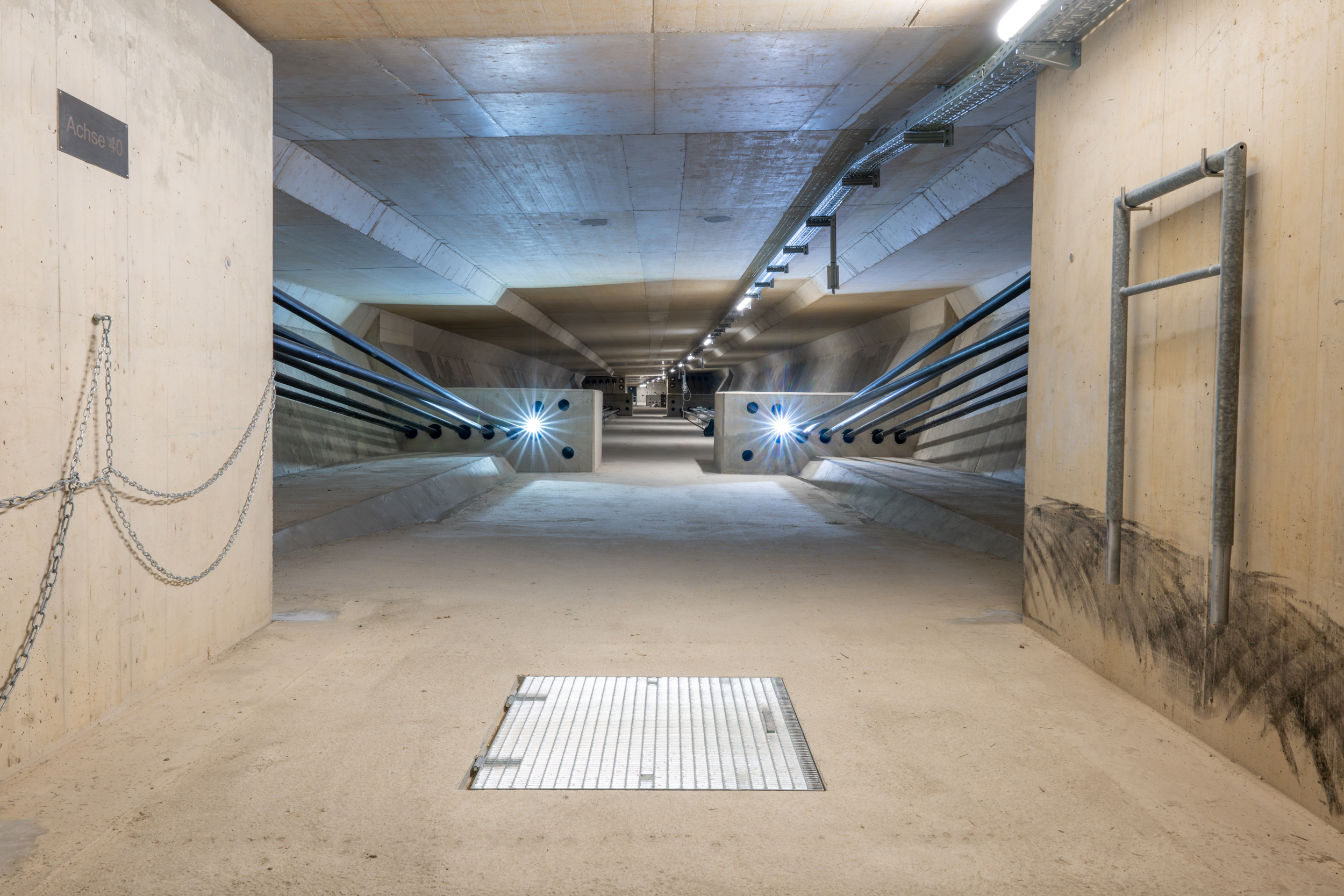
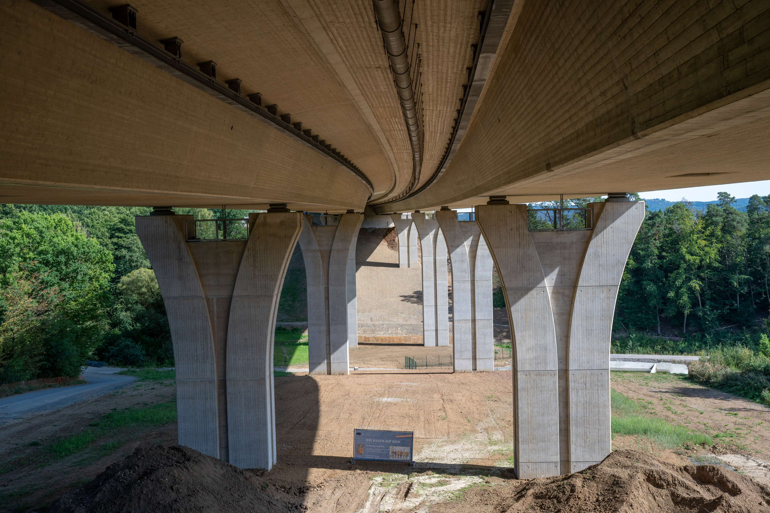
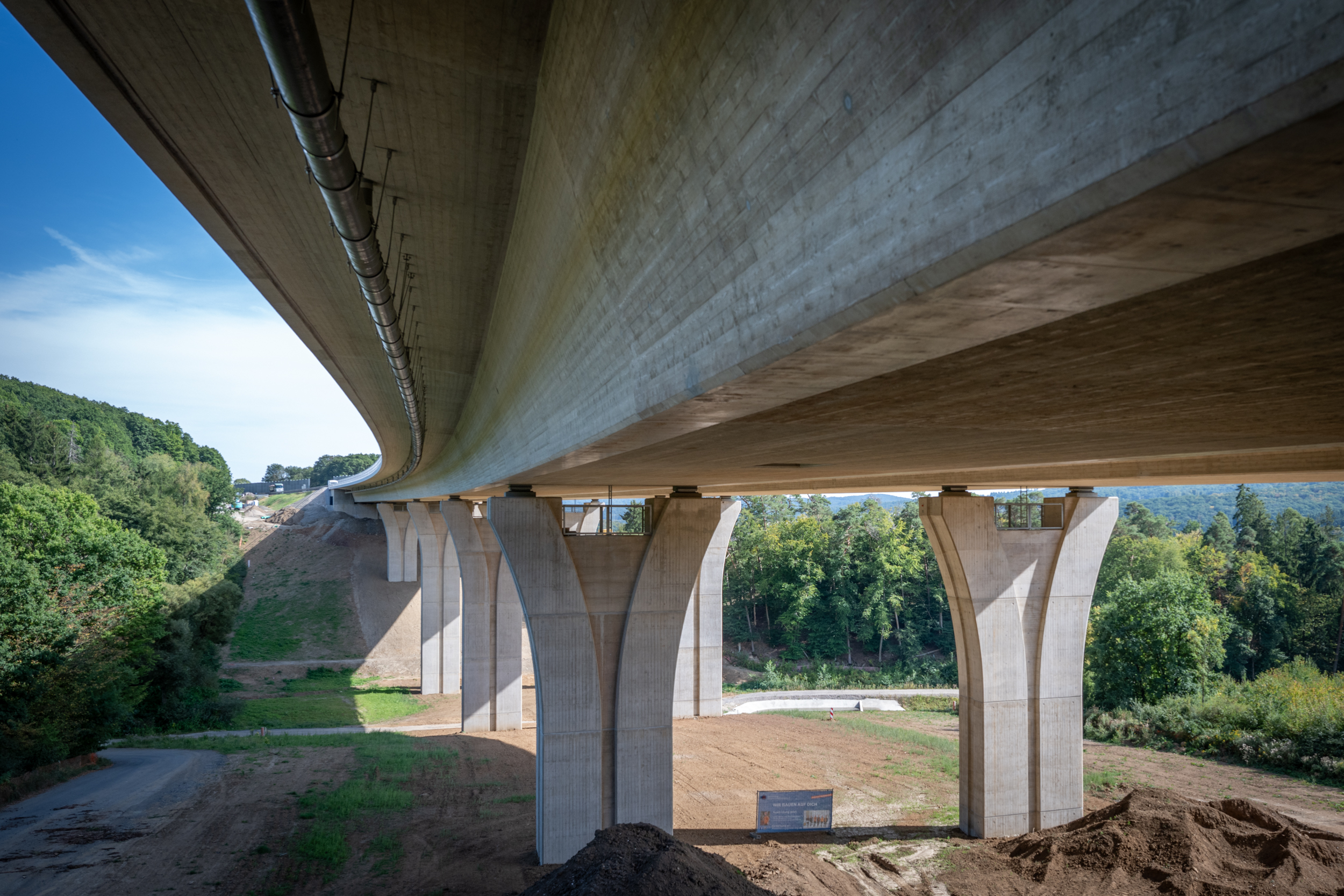
As part of the 6-lane expansion of the BAB 45, the Onsbach Valley Bridge replaces the previous structure from 1968/1969. The new Onsbach Valley Bridge has a length of 295.0 m, a width of 36.60 m between the railings and a height above the valley of approx. 30.0 m. The separate superstructures are designed as longitudinally prestressed continuous concrete beams in composite construction with a constant structural height of 3.60 m over five fields with spans of 50.0 m – 63.0 m – 65.0 m – 65.0 m 52.0 m. The superstructure cross-section consists of a single-cell hollow box for each directional lane. The Onsbach Valley Bridge is aligned in a radius with an attached clothoid. The carriageway has a variable crossfall of between 3.3% and 4.5%. The longitudinal fixed point of the bridge is located on the Dortmund abutment. A finger joint construction is planned as a transition structure on the Hanau abutment.
Special features
The superstructures are manufactured on a replacement radius and taking into account the variable crossfall of the carriageway slab using the incremental launching method. To reduce the stresses in the construction state, auxiliary piers are provided in each field, some of which are transversely displaced for the production of the second directional carriageway.
Two longitudinally fixed bearings are planned on the Dortmund abutment, each of which is designed for 70% of the total horizontal load for the final state. In addition, each bearing is designed for the complete horizontal load in the bearing replacement load case in the raised state (lifting dimension 1.0 cm) for bearing replacement.
Due to the very unfavorable force ratio between the minimum vertical load and the maximum horizontal load, the anchor plates of the longitudinally fixed bearings receive massive tie rod anchors, which would have to be installed on the abutment before the start of the superstructure launching and on the superstructure in the launching cell.
To ensure a sufficient load on the brake caliper to guarantee the stability of the superstructure via friction and to ensure the transfer of force from the lifting jacks when launching the abutment, the auxiliary support in the first field is press-controlled in front of the launching system.
The Hanau carriageway is launched from the launching cell behind the Dortmund abutment at an incline of approx. 1%. The Dortmund carriageway is launched from the Hanau launching cell at an incline of approx. 1% downhill.
As a result, the temporary fixed point (brake caliper) for the Dortmund carriageway is initially located on the Hanau abutment. After the earth has been moved, the fixed point of the bridge must be relocated to the final longitudinally fixed bearings on the Dortmund abutment.
The bored pile foundation of the Hanau carriageway on the Hanau abutment is located in the area of an old quarry. The highly load-bearing greywacke jumps here almost vertically by approx. 12.0 m.
The one-piece, transversely prestressed abutments of the existing bridge had to be separated for the new construction while maintaining traffic in the BAB axis. Extensive upgrade measures were required to ensure the overall stability of the remaining abutment under traffic.